Digital Switching
The primary goal of Digital Switching Systems (DSS) is to enhance the styling and flexibility of the user interface at the helm while reducing its footprint on the dash. As we will see shortly, the DSS solution improves overall vehicle electrical system functionality and flexibility through powerful microprocessor programming and convenient expansion for larger applications. As an added advantage, the DSS allows the user to significantly reduce labour and material expenditures associated with installing and maintaining traditional mechanical switches.
Wiring can be reduced by as much as 60 percent and wire connections can be reduced by as much as 50 percent.
Digital Switching Systems (DSS) Basics: How Does the System Work?
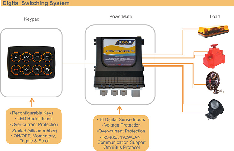
The two primary components of the system are the keypad/s and the Power Management
Enclosure (PME). The keypad is the component that usually functions as a “dumb terminal” for accepting user inputs. It sends unique software codes to the PME for each make and break of its internal dome switches. Conversely, the keypad receives system status information from the PME that typically includes function indicator, overload fault, and backlight information.
The main components of a keypad are the keypad rubber (usually laser etched with customer specified artwork), a printed circuit board, multiple dome switch contacts, and an 8-bit RISC microcontroller. The switch contacts are metal domes with gold plating on the contact side that are typically placed onto the gold plated PCB. All dome switches are rated to 3 million cycles for maximum reliability.
The power management enclosure (PME) typically is the “smart” component of the DSS. It receives instruction codes from the keypad and processes them based on the current system status. The PME uses low voltage digital switching to control the operation of a variety of marine/transportation vehicle accessories, including lights, pumps, blowers, heaters, and aerators.
Most DSS technology on the market today either employs electromechanical or solid state means to perform the switching and current overload protection. For electromechanical PMEs, the switching is typically done by mechanical relays while overload protection is normally provided by conventional reset-able circuit breakers.
In the case of the solid state PME, a current-sensing semiconductor switch such as a power MOSFET is responsible for both the switching and current limit protection. The normal DC operating voltage for most PMEs is either 12 or 24 volts, and all commercially available units are ignition protected per U.S. Coast Guard 33 CFR 183.410, ISO-8846, and SAE J1171.

The DSS Communications Interface: Electrical Noise Immunity is Built In!
Since the DSS technology uses low voltage digital switching, the communication link between the PME and the keypads is accomplished via a simple, low current, four-wire interface. It consists of four signals: Power, Ground, and the differential pair signals of TXRX+ and TXRX-. In typical communication applications, the transmission (TX) and reception (RX) codes run back and forth across two separate wires. Within the DSS, the logic codes run simultaneously between the keypad and PME across the same two wires in both directions (TXRX- & TXRX+), allowing for a significant voltage swing (typically 10 volts) between a logic “0” and a logic “1”. Thus, the benefit of the differential pair to the DSS user is that it helps eliminate any communication errors due to electrical noise that might be present in the application.
IF8 Interface Boards: Discrete Switches Can Be Used With the DSS!
The DSS Interface Board allows users to integrate any discrete switch with the DSS. The board senses any user actuation of a connected discrete switch and, similar to the keypad, sends a unique software code to the PME to request that an electrical operation be performed.
Remote discrete switches, in conjunction with dual keypad functions at a vehicle helm, can form a three-way switch that conveniently controls an electrical function from two different locations on the vehicle.
One IF board accepts up to eight switches and multiple IF boards can be connected to accommodate additional switches. As an added feature, the IF board supports switches with backlights and indicators.
In Summary: DSSA Has It All!
The Digital Switching System technology is an ideal choice for those customers who desire unlimited flexibility and versatility. The flexibility realises itself in that a typical system can have any number of keypads and PMEs. Versatility is achieved because the DSS technology is microprocessor- based and it can be programmed to perform a virtually limitless array of functions. In addition, DSS has refined the technology so that semi-custom Keypad/PME system packages can be created to fit virtually every cost budget.


